
In the new digital environment, national and global brands must field applications that are always-on and perform in near real-time. This has led to the adoption of distributed technology for applications as well as the databases serving those applications. In order to best serve a wide geography and to gain higher levels of availability, organizations have distributed their digital presence across geographies, whether data centers of their own, or the zones represented by the public cloud vendors, or a combination of both. In order to tackle the challenges of maintaining a global view of business transactions that occur in this distributed realm, Aerospike supports two distinct active-active deployment models, multi-site clustering and cross datacenter replication (XDR):
Multi-site clustering uses synchronous replication to deliver a global distributed transaction capability by spanning a single Aerospike cluster across multiple geographically distributed sites.
Cross-datacenter replication (XDR) uses asynchronous replication to connect two or more Aerospike clusters located at multiple geographically distributed sites.
Both models above are active-active and enable Aerospike to be used in a wide variety of transactional use cases.
Multi-site Clustering
In a multi-site clustering configuration, the nodes comprising a single Aerospike cluster are distributed across sites. A site can be a physical rack in a datacenter, an entire datacenter, an availability zone in a cloud region, or a cloud region. Here are a few examples:
A single cluster with two racks, the first rack in an availability zone in Amazon US West region and the second rack in a different availability zone also in Amazon West region.
A single cluster with three racks, the first in Amazon US West region, the second in Amazon Central region and the third in Amazon East region.
A single cluster with two racks, the first rack in a data center in Rome, Italy, and another rack in a close by data center (eight kilometers away) also in Rome.
A single cluster with three racks, one rack in a datacenter in San Francisco, a second rack in a datacenter in New York, and a third rack in a data center in Dallas.
In all four examples, it is assumed that every rack has the same number of homogeneous nodes, so system capacity per rack is identical. A common practice is to ensure that the replication factor is set equal to the number of racks. A multi-site cluster relies on the distributed clustering algorithms intrinsic to Aerospike itself, independent of the distance between sites.
With an Aerospike cluster configured for Strong Consistency (SC), a multi-site cluster guarantees that all writes will be replicated across sites without data loss. The write logic is shown in Figure 1. All application writes are sent to the node that contains the master copy of the partition which then coordinates a two-phase write process with every replica before the system returns success to the client. In case a write to one of the replicas fails, the master will ensure that the write is completed to the appropriate number of replicas within the cluster (or sub cluster in case the system has been compromised.) Also, note that the Advice Replicated messages are not sent for replication factor 2 in most circumstances (exception being the case where the acting master isn’t a replica).
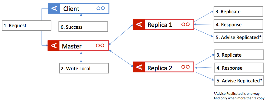
Figure 1: Synchronous write logic.
Such a system can survive the loss of an entire site (rack) with no loss of data and continue to operate. Therefore, such a cluster is an active/active configuration with both strong consistency and availability during site failure scenarios.
The main trade-off is dealing with low latency of writes and reads.
Application’s writes might experience additional latency depending on the effective distance between the two sites, whether actual physical distance or latency as a cause of network configuration. For example, latency could be as little as a couple of milliseconds of additional latency for sites that are a few miles apart on the ground to increased latency because of sites that are thousands of miles apart via satellite links.
Applications running on a given site can be configured to read with low latency from the rack located at the same site because an entire copy of the cluster’s data is available in nodes in the local rack.
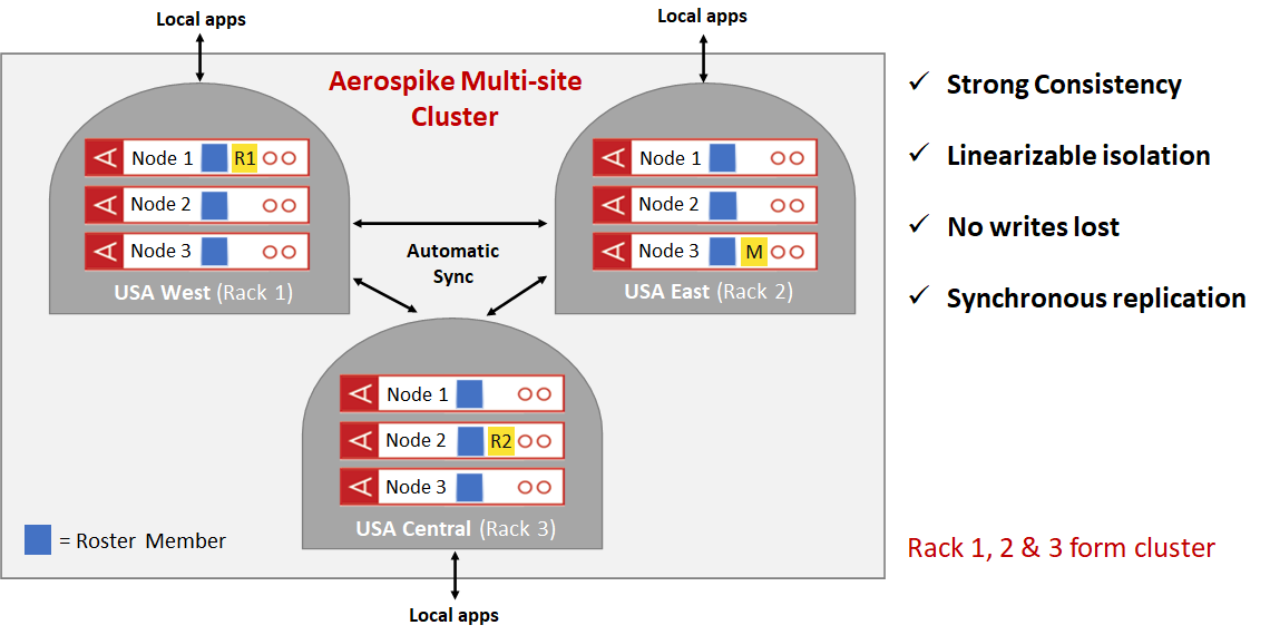
Figure 2: Multi-site clustering – 3 replicas, 3 sites
The cluster illustrated in Figure 2 consists of three racks in three sites with a replication factor of 3. Therefore in this case, every site has a full copy of the datas. Reads are localized per site to maintain low read latency and write latency can be anywhere from a couple of milliseconds to a few hundred milliseconds depending on the geographic location of the sites and the distance between them.
A cluster such as the above will preserve strong consistency, avoids data loss and preserves availability on single site failures. In Figure 3, Rack 3 is disconnected from the cluster and forms a split brain with racks 1 and 2 forming the majority sub-cluster and rack 3 forming a minority sub-cluster. Using information in the Roster that is shared between all of the nodes of the original cluster, the system uses the strong consistency algorithm of Aerospike to ensure that there are no writes lost, and no operator intervention. The majority sub-cluster comprising racks 1 and 2 continues to take both reads and writes while creating a temporary third copy of data items that are being written during the split-brain event. The minority sub-cluster remains up but is unavailable for application reads and writes. Once the network split is repaired, the nodes of rack 3 join with the rest of the nodes and form a complete cluster comprising racks 1, 2 and 3. At this point, the third copy of the items updated during the split brain event are properly transferred to the appropriate nodes in rack 3 so that the system can revert to steady state. All of this happens with no operator intervention, preserving strong consistency with no data loss and complete availability during the split brain event. There are many such failures that are handled automatically ensuring that most site failure events are handled automatically.
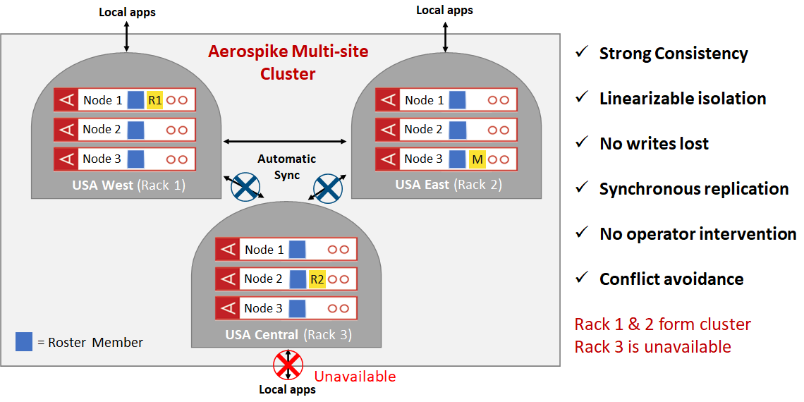
Figure 3: Multi-site clustering – site disconnected
With multi-site clustering, Aerospike Database 5 delivers strong consistency, geographic data distribution, elasticity and performance, making it the best choice for any enterprise that requires a geographically distributed transactional system at scale. Aerospike multi-site clustering is built on a real-time, always-on, active-active architecture, enabling a new class of use cases for global enterprises where the requirements for strong consistency, elastic scaling, high performance and resiliency are non-negotiable.
Multi-site clustering uniquely combines strong consistency with support for large scale, globally distributed transactional applications that are able to relax the write latency, which varies based on the distance between sites of a cluster, while still delivering sub-millisecond read latency at high throughput. As described earlier, Aerospike multi-site clusters can be architected to survive site failures with no operator intervention while, at the same time, delivering strong consistency with zero data loss via conflict avoidance. This eliminates the need for application complexity and/or human involvement in resolving conflicts.
Cross-Datacenter Replication (XDR)
Aerospike Database 5 delivers a new XDR (Cross Datacenter Replication) implementation based on an active-active architecture with asynchronous replication between clusters located at different geographically distributed sites. A site can be a physical rack in a datacenter, an entire datacenter, an availability zone in a cloud region, or a cloud region. Here are some examples.
Example configuration | Explanation and topology type |
One cluster in an availability zone in Amazon US West region configured to ship all of its data updates to a second cluster in a different availability zone also in Amazon West region. | One-way shipping is configured between the clusters. This is a typical active-passive setup where the second cluster is sometimes described as a “hot standby”. |
A two-cluster system where each cluster is configured to ship all of its data updates to the other, the first cluster in Amazon US West region and the second in Amazon East region. In this case, applications can be configured to use either cluster for both reads/updates. | A two-way shipping configuration. This configuration can be characterized as active/active. |
A three-cluster cross-cloud active/active system, one cluster in an Azure datacenter in the US West region, a second cluster in Amazon US Central region, and a third cluster on Google Cloud US East region. | A three-way shipping configuration. This configuration can be characterized as active/active. |
XDR (active/active or active/passive) can extend the data infrastructure to any number of clusters with control, flexibility, ease of administration, faster writes, and regional autonomy.
The new XDR shipping algorithm is based on a record’s last-update-time (LUT) resulting in simpler and efficient metadata management than the logging mechanism used in earlier XDR versions. LUT-based shipping allows easy resynchronization of a data center starting at a specific point of time in the past. Furthermore, the new XDR supports dynamic configuration of and independent shipping between any pair of source and target sites.
Often there is a natural separation of datasets on a geographic or some other basis. In these cases writes in one region that need to be replicated to another have a very low probability of conflicting with plesiochronous writes in the other site. For use cases that can operate with a level of relaxed consistency, it may be best to optimize the write and read times for the bulk of the transactions by handling potential inconsistencies caused by write conflicts within the application code. For these use cases and others, XDR can support sub-millisecond latency for both reads and writes.
Dealing with conflicting updates
Even in an active-passive setup with the source cluster configured with strong consistency, there is still work to be done in terms of metadata exchange to ensure that the data in the source (active) cluster is perfectly synchronized with the data in the destination (passive) cluster.
In an active/active setup (example configuration 2 and 3 above), the asynchronous nature of the replication mechanism could cause a consistency issue if concurrent updates are made to the same data record in multiple sites at the same time, also known as conflicting writes.
Assuming the entire record is shipped on every write, inconsistencies can occur. The changed record at one site could be in-transit via XDR to the other site, while the changed record on the other site is simultaneously shipped by XDR to the first site. The result is either the record ends up having different values on the two clusters or one of the two updates is lost (assuming some kind of timestamp-based resolution of the conflict).
There are ways to mitigate this situation. For example, the XDR shipping mechanism might work at the bin level, tracking bin update times in addition to record update times. This technique, known as bin projection, will ensure that different bins of the same record can be changed concurrently at different sites without violating data consistency. It should be possible to merge the records properly on both sites using bin level update times.
Even with shipping bin level changes, concurrent changes to the same bin in multiple sites can result in inconsistencies analogous to those described above for the record level. We will either end up with two different values for the bin in the two sites or one of the two values will be lost.
An often suggested alternative is the conflict-free replicated data type (CRDT). However, consistency approaches such as CRDTs only apply to a small subset of data types, typically counters and sets, and do not help with most other data types. Network interruptions, which are amplified over distance, as well as nodes, zones or regions going down all ensure that data inconsistencies will happen, and that writes will be lost.
One possible way to guarantee consistency in most cases for an active/active XDR deployment is to architect the application’s data access in such a way that conflicts on specific data items (records or bins) are completely avoided.
However, if write conflicts are allowed, the application needs to tolerate some level of consistency violations. The asynchronous nature of the shipping algorithms means that when a site failure occurs, the most recent updates from the failed site will not be available at the other sites. This means applications need to be designed and prepared to handle possible loss of data.
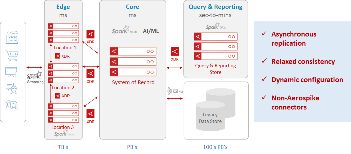
Figure 4: Aerospike data hub using XDR
Aerospike’s XDR enables enterprises to create a global data hub (Figure 4) that automatically routes and augments data captured anywhere in the data center to wherever it’s needed – whether in Aerospike clusters or any other data repository. Typically, regulatory compliance is highly regional and the new XDR provides the ability to manage regulatory requirements such as GDPR and CCPA on a regional basis.
Summary
Aerospike can be run in active/active configurations with either multi-site clustering or XDR.
Running an active/active multi-site cluster preserves strong consistency with no data loss and provides 100% availability during site failures. However, this scheme results in additional write latencies that could be anywhere from 2 to 100 milliseconds, depending on the distance between sites.
Running an active/active system with XDR provides applications with low-latency reads and writes, but applications might need to compromise on consistency guarantees during site failures. Furthermore, the application’s data access patterns need to be designed carefully to ensure that concurrent write conflicts do not result in application-level inconsistencies.
Both multi-site clustering and the new XDR work regardless of whether the data is stored in a private cloud, a public cloud or any combination of both. With these features, customers can now easily deploy powerful mission-critical systems in the most resilient manner according to their business needs. This choice of active/active topologies gives Aerospike users the flexibility they need for their mission-critical applications.
LEARN MORE:
Solution Brief: Aerospike Multi-site Clustering
Solution Brief: XDR for Aerospike Database 5
Blog: Aerospike Database 5: Multi-site Clustering and Cross Datacenter Replication
White Paper: Aerospike Multi-site Clustering: Globally Distributed, Strongly Consistent, Highly Resilient Transactions at Scale
Keep reading

Jul 16, 2026
Available and still failing: Why healthy dashboards hide tail latency

Jun 17, 2026
Fail fast, stay resilient: How to stop hidden gray failures in Aerospike on AWS EBS

May 28, 2026
Determining the best machine learning and AI databases

May 18, 2026
The three price tags: How Redis unpredictability costs you infrastructure, engineering time, and UX